
Direct bottle transfer
The air conveyor connects directly to the transfer wheel, reducing screw and chain adjustments during bottle-format changes.
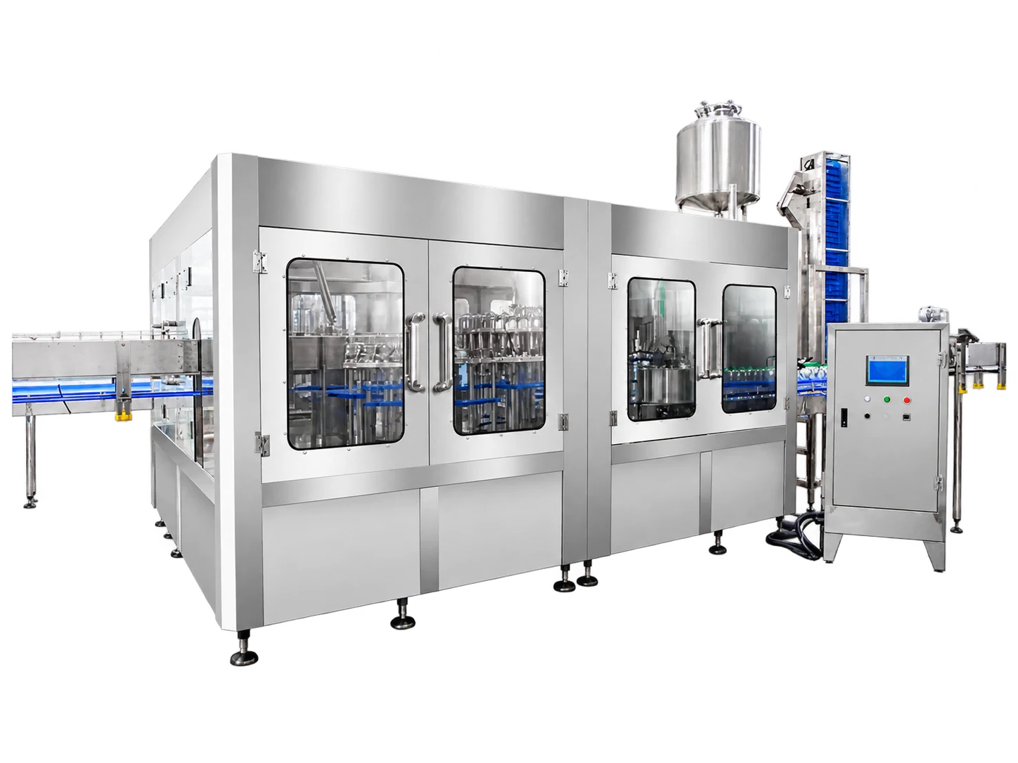
Rinse · Fill · Cap / PET Bottled Water
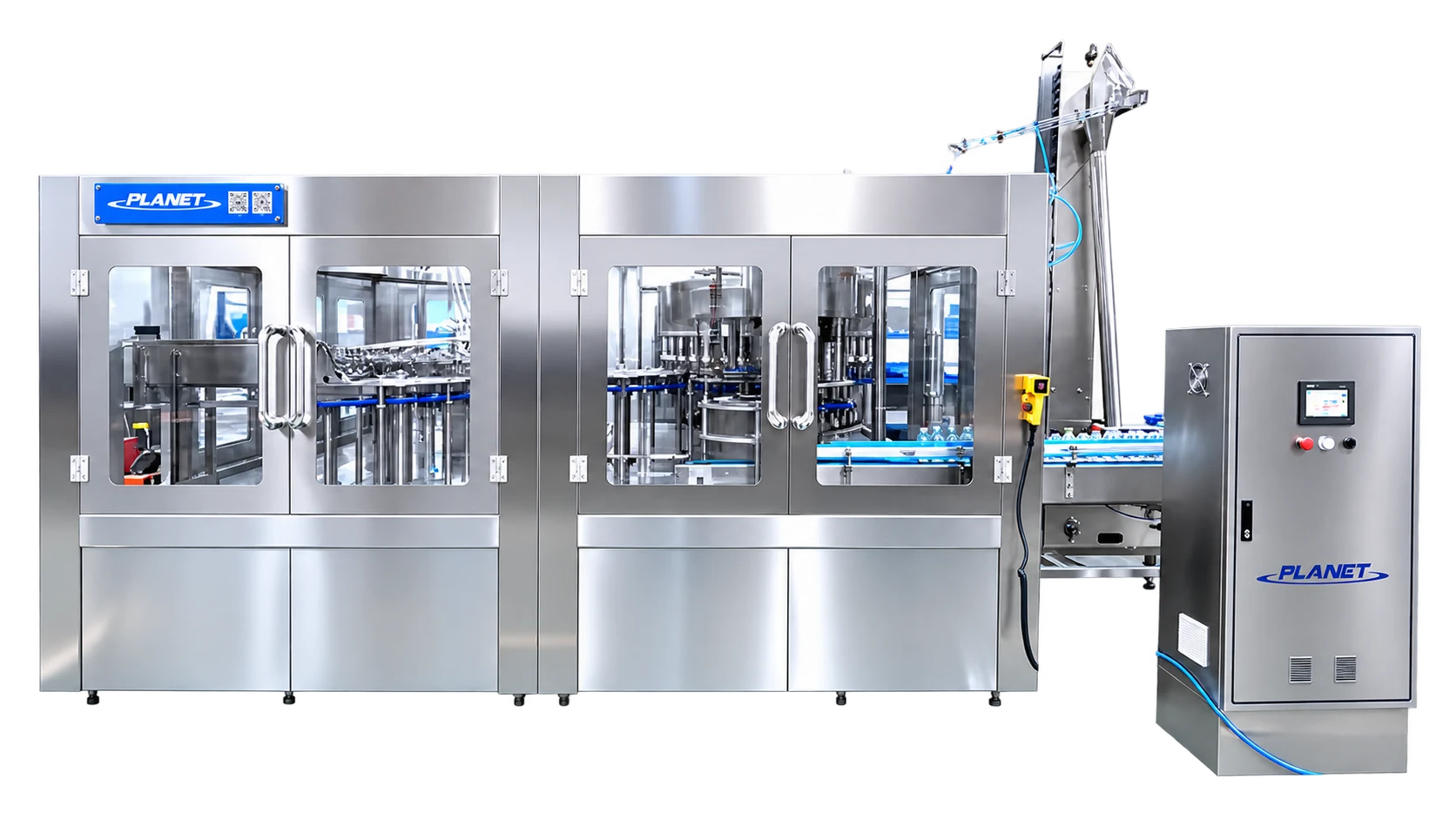
An automatic three-in-one line for mineral, drinking and purified water. Compare nine published CGF models, bottle formats and the equipment that connects the line.
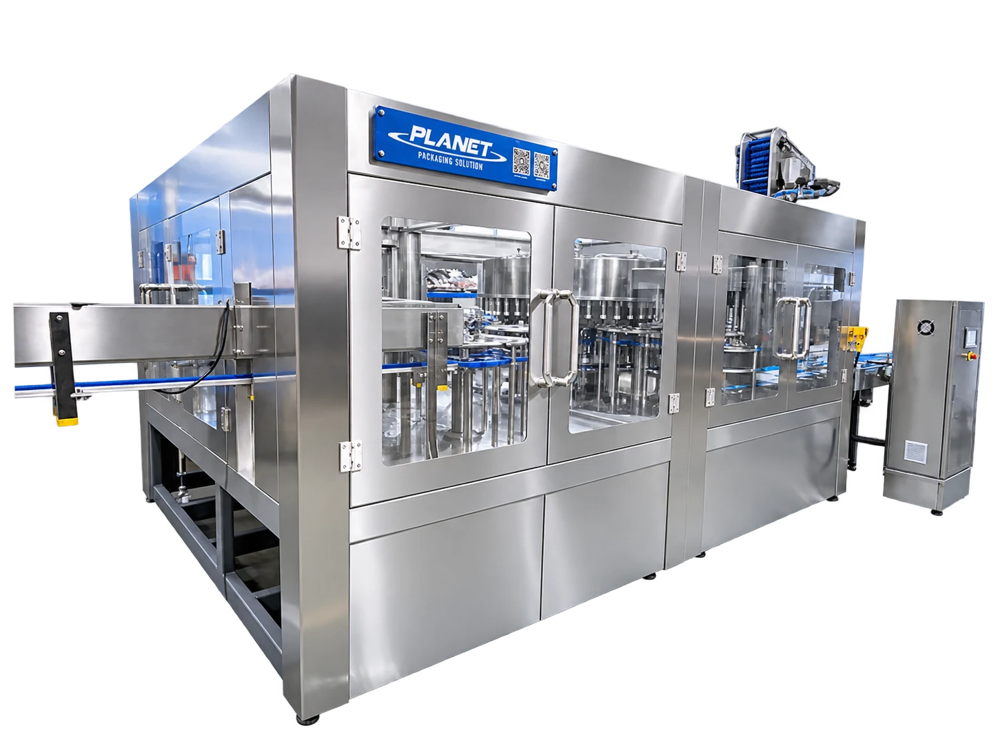
Production video
10,000 BPH Rinse, fill and cap
Watch the bottled-water production line shown in the original video, then compare machine models for your bottle and target output.
Published product parameters
Nine models are listed on the source page. Output, dimensions and utilities are published reference values; confirm the final configuration against your bottle and acceptance conditions.
| Model | Washing heads | Filling heads | Capping heads | Capacity | Power | Dimensions (L × W × H) | Weight |
|---|---|---|---|---|---|---|---|
| CGF14-12-5 | 14 | 12 | 5 | 4,000–5,000 BPH | 3 kW | 2360 × 1770 × 2350 mm | 2,000 kg |
| CGF18-18-6 | 18 | 18 | 6 | 8,000–9,000 BPH | 3.5 kW | 2930 × 2150 × 2450 mm | 4,200 kg |
| CGF24-24-8 | 24 | 24 | 8 | 10,000–12,000 BPH | 5 kW | 3300 × 2250 × 2450 mm | 5,500 kg |
| CGF32-32-8 | 32 | 32 | 8 | 13,000–15,000 BPH | 5 kW | 3430 × 2650 × 2450 mm | 6,500 kg |
| CGF40-40-10 | 40 | 40 | 10 | 15,000–18,000 BPH | 9 kW | 4430 × 3280 × 2450 mm | 9,500 kg |
| CGF50-50-15 | 50 | 50 | 15 | 22,000–24,000 BPH | 9 kW | 4720 × 3550 × 2450 mm | 15,000 kg |
| CGF60-60-15 | 60 | 60 | 15 | 28,000–30,000 BPH | 13 kW | 6000 × 5450 × 2550 mm | 18,000 kg |
| CGF72-72-18 | 72 | 72 | 18 | 33,000–36,000 BPH | 18 kW | 6500 × 4680 × 2550 mm | 25,000 kg |
| CGF80-80-22 | 80 | 80 | 22 | 40,000–42,000 BPH | 23lw | 7800 × 6380 × 2550 mm | 27,000 kg |
The legacy page lists the CGF80 power as “23lw”; this apparent typo is retained in the table pending confirmation. Its product introduction gives a narrower output range than the nine-model table.
02 / Applicable bottle type
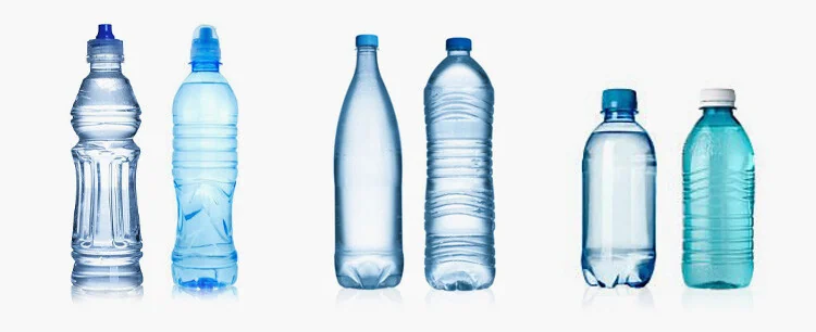
Published bottle-format range
Retained and edited for clarity from the original bottle-type section.
The air conveyor connects directly to the transfer wheel, reducing screw and chain adjustments during bottle-format changes.
Bottles are held at the neck. Format changes focus on the guide plate, star wheel and nylon change parts rather than the equipment height.
Stainless-steel washing grippers avoid contact with the bottle mouth to reduce the risk of secondary contamination.
High-flow filling valves are designed for fast, accurate filling with reduced product loss.
The spiral bottle outlet is designed to avoid conveyor-height adjustment when changing bottle formats.
The main machine uses PLC-based automatic control.
03 / Machine layout
The original layout illustration shows the filling machine in the context of blowing, water treatment, drying, labeling, packing and collection.
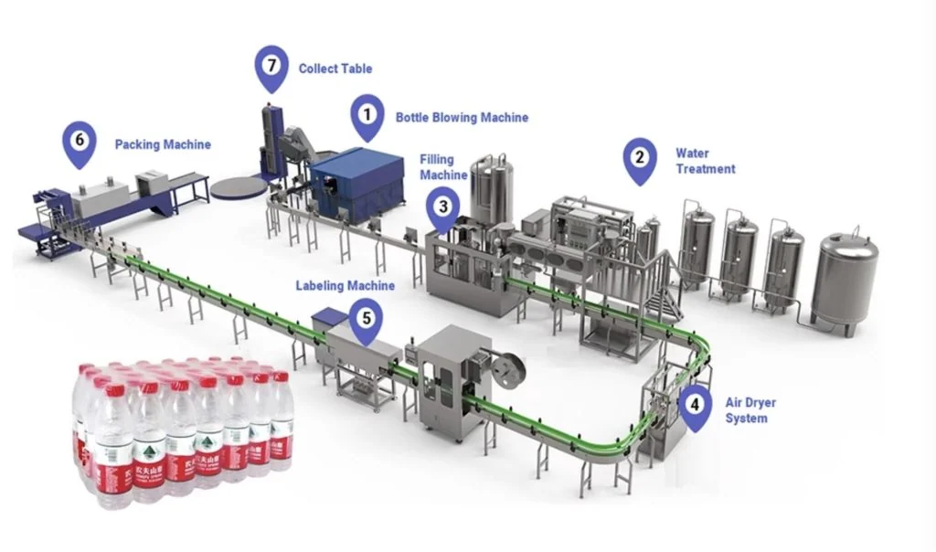
Automatic bottle blowing machine
Air conveyor system
3-in-1 washing, filling and capping machine
Bottle conveyor system
Automatic line equipment
Sleeve labeling machine
Film shrink packer or carton packer
Inside the process
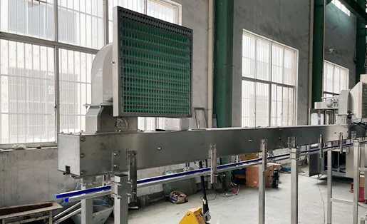
Neck-held bottles move from the blowing stage into the filling machine by air flow.
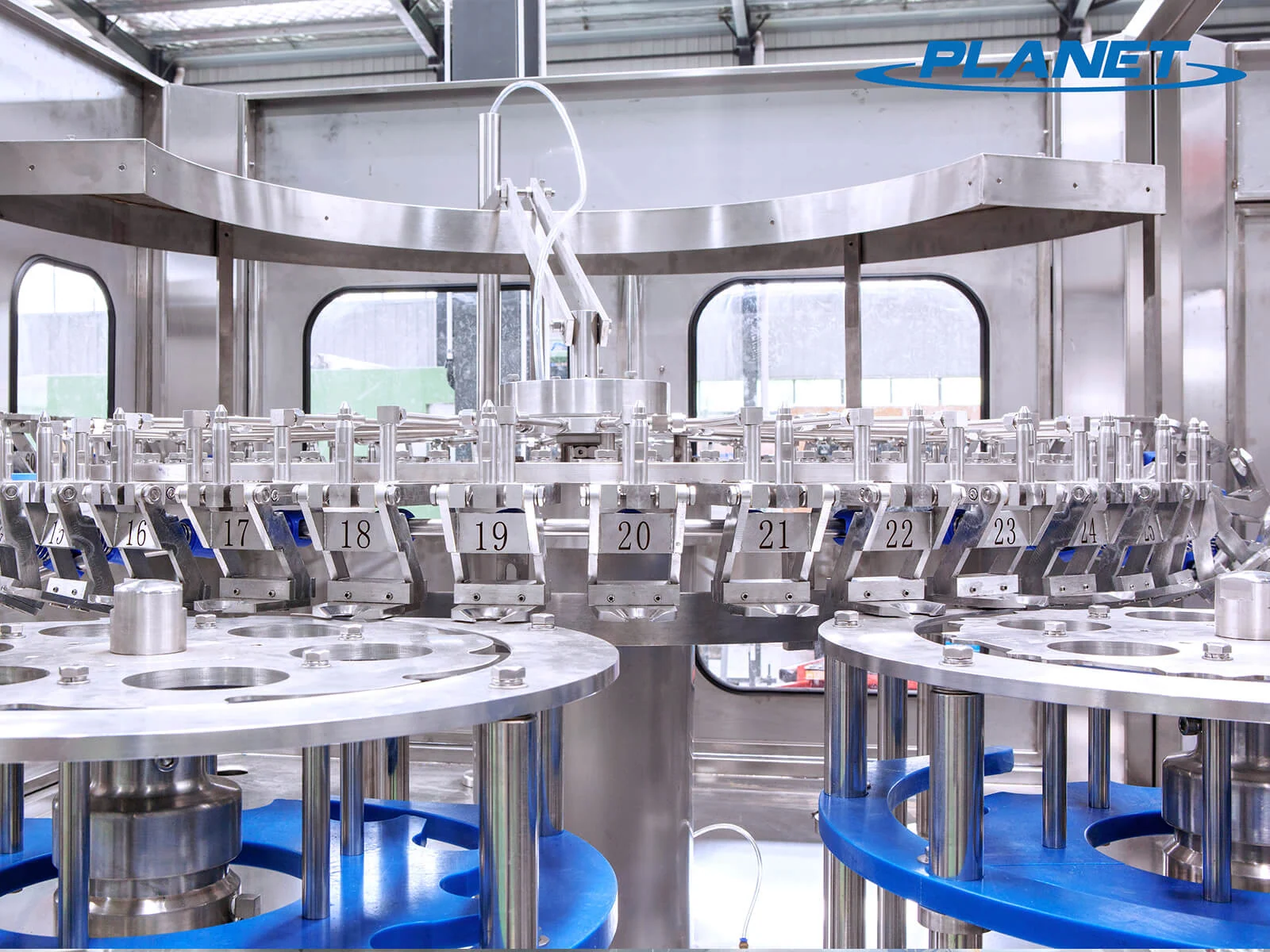
The air conveyor feeds directly into the bottle infeed dial for rinsing.
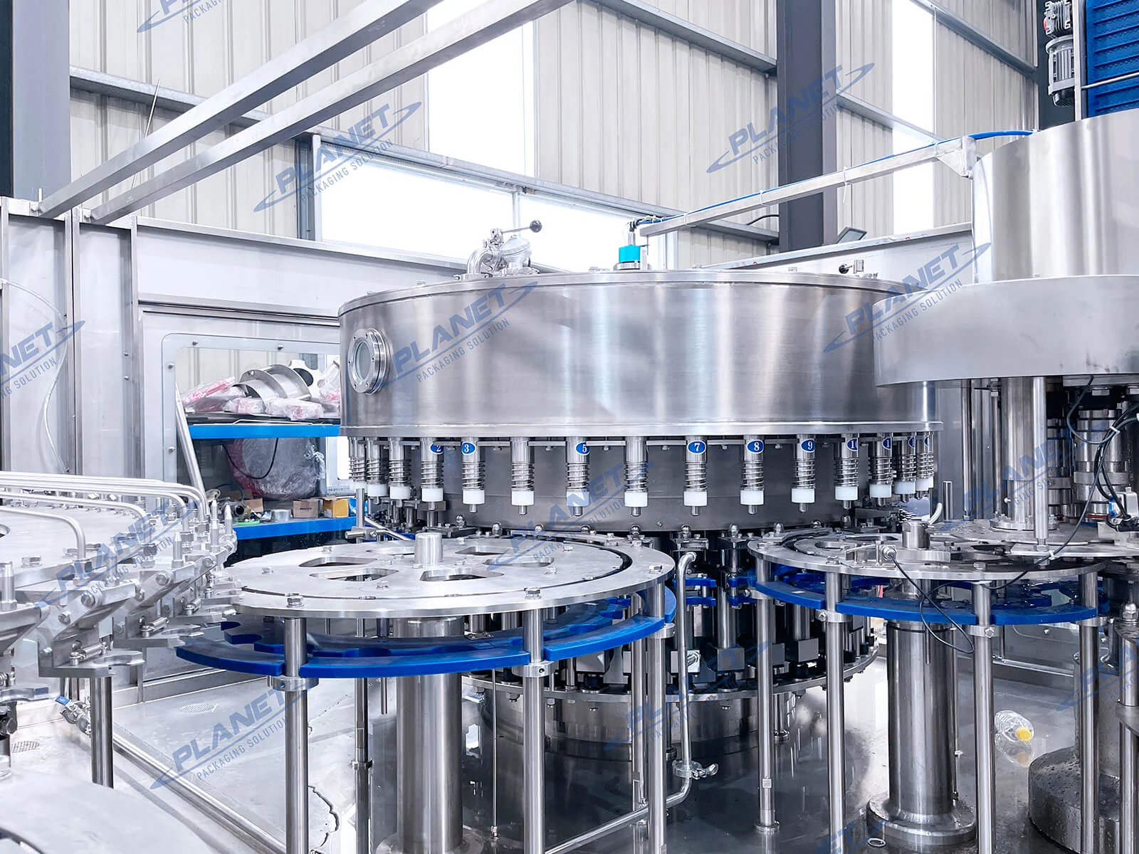
The filling station is designed to keep fill levels consistent across bottles.
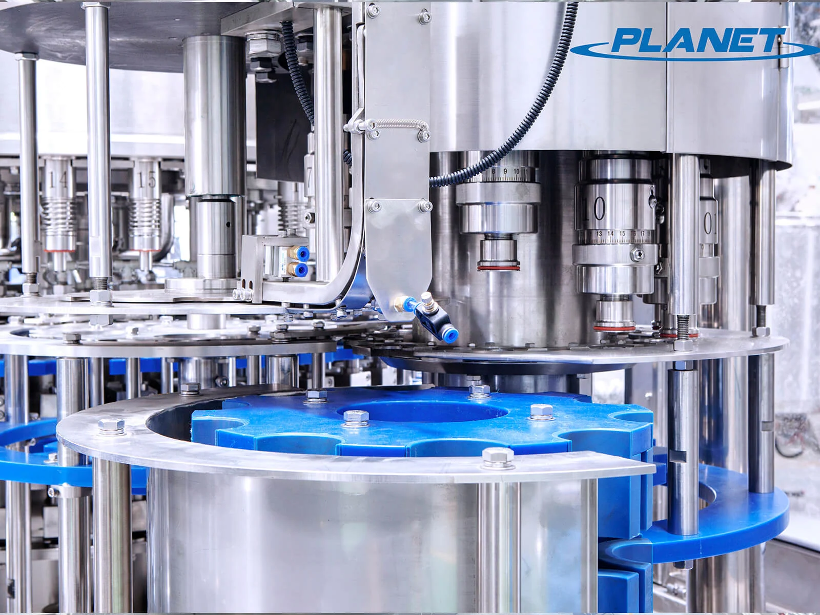
Electromagnetic capping heads complete the rinse–fill–cap sequence.
Turn-key solution
Beyond the filler, the original line brief lists container handling, labels, packing, palletizing and site requirements. These choices are specified for the project rather than implied by a single machine model.
Discuss your lineRelated equipment
Project inquiry
 5–19L Water Filling Machine
 Juice Filling Machine
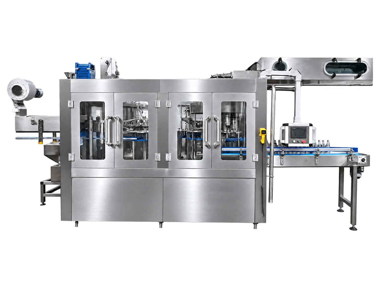 Carbonated Beverage Filling Machine